电机原理及驱动:电机学基础
电机原理及驱动:电机学基础基本信息
| 书 名 | 电机原理及驱动 | 作 者 | 查普曼 (Stephen J.Chapman) |
|---|---|---|---|
| 类 型 | 科技 | 出版日期 | 2013年6月1日 |
| 语 种 | 英语, 简体中文 | ISBN | 9787302322481 |
| 品 牌 | 清华大学出版社 | 外文名 | Electric Machinery Fundamentals(Fifth Edition) |
| 译 者 | 满永奎 | 出版社 | 清华大学出版社 |
| 页 数 | 534页 | 开 本 | 16 |
| 定 价 | 69.00 | ||
Chapter 1 Introduction to Machinery Principles
1.1 Electrical Machines, Transformers, and Daily Lite
1.2 Rotational Motion, Newton's Law, and Power Relationships Angular Position θ / Angular Velocity ω / Angular Acceleration α / Torque τ / Newton's Law of Rotation / Work W/Power P
1.3 The Magnetic Field
Production of a Magnetic Field / Magnetic Circuits / Magnetic Behavior of Ferromagnetic Materials / Energy Losses in a Ferromagnetic Core
1.4 Faraday's Law——Induced Voltage from a Time—Changing Magnetic Field
1.5 Production of Induced Force on a Wire
1.6 Induced Voltage on a Conductor Moving in a Magnetic Field
1.7 Real, Reactive, and Apparent Power in Single—Phase AC Circuits Alternative Forms of the Power Equations / Complex Power / The Relationships between Impedance Angle, Current Angle, and Power / The Power Triangle
1.8 Summary
Questions
Problems
References
Chapter 2 Transformers
2.1 Why Transformers Are Important to Modern Life
2.2 Types and Construction of Transformers
2.3 The Ideal Transformer
Power in an Ideal Transformer/Impedance Transformation through a Transformer / Analysis of Circuits Containing Ideal Transformers
2.4 Theory of Operation of Real Single—Phase Transformers The Voltage Ratio across a Transformer / The Magnetization Current in a Real Transformer / The Current Ratio on a Transformer and the Dot Convention
2.5 The Equivalent Circuit of a Transformer The Exact Equivalent Circuit of a Real Transformer / Approximate Equivalent Circuits of a Transformer / Determining the Values of Components in the Transformer Model
2.6 The Per—Unit System of Measurements
2.7 Transformer Voltage Regulation and Efficiency The Transformer Phasor Diagram / Transformer Efficiency
2.8 Transformer Taps and Voltage Regulation
2.9 The Autotransformer
Voltage and Current Relationships in an Autotransformer / The Apparent Power Rating Advantage of Autotransformers / The Internal Impedance of an Autotransformer
2.10 Three—Phase Transformers
Three—Phase Transformer Connections / The Per— Unit System for Three—Phase Transformers
2.11 Transformer Ratings and Related Problems
The Voltage and Frequency Ratings of a Transformer / The Apparent Power Rating of a Transformer / The Problem of Current Inrush / The Transformer Nameplate
2.12 Instrument Transformers
2.13 Summary
Questions
Problems
References
Chapter 3 AC Machinery Fundamentals
3.1 A Simple Loop in a Uniform Magnetic Field The Voltage Induced in a Simple Rotating Loop / The Torque Induced in a Current—Carrying Loop
3.2 The Rotating Magnetic Field Proof of the Rotating Magnetic Field Concept / The Relationship between Electrical Frequency and the Speed of Magnetic Field Rotation / Reversing the Direction of Magnetic Field Rotation
3.3 Magnetomotive Force and Flux Distribution on AC Machines
3.4 Induced Voltage in AC Machines
The Induced Voltage in a Coil on a Two—Pole Stator / The Induced Voltage in a Three—Phase Set of Coils / The RMS Voltage in a Three—Phase Stator
3.5 Induced Torque in an AC Machine
3.6 Winding Insulation in an AC Machine
3.7 AC Machine Power Flows and Losses
The Losses in AC Machines / The Power—Flow Diagram
3.8 Voltage Regulation and Speed Regulation
3.9 Summary
Questions
Problems
References
Chapter 4 Synchronous Generators and Motors
4.1 Synchronous Generator Construction
4.2 The Speed of Rotation of a Synchronous Generator
4.3 The Internal Generated Voltage of a Synchronous Generator
4.4 The Equivalent Circuit of a Synchronous Generator
4.5 The Phasor Diagram of a Synchronous Generator
4.6 Power and Torque in Synchronous Generators
4.7 Measuring Synchronous Generator Model Parameters
The Short—Circuit Ratio
4.8 Synchronous Generator Ratings
The Voltage, Speed, and Frequency Ratings / Apparent Power and Power—Factor Ratings / Synchronous Generator Capability Curves / Short—Time Operation and Service Factor
4.9 Basic Principles of Motor Operation
The Equivalent Circuit of a Synchronous Motor / The Synchronous Motar from a Magnetic Field Perspective
4.10 Steady—State Synchronous Motor Operation
The Synchronous Motor Torque—Speed Characteristic Curve / The Effect of Load Changes on a Synchronous Motor / The Effect of Field Current Changes on a Synchronous Motor / The Synchronous Motor and Power—Factor Correction / The Synchronous Capacitor or Synchronous Condenser
4.11 Starting Synchronous Motors
Motor Starting by Reducing Electrical Frequency / Motor Starting with an External Prime Mover / Motor Starting by Using Amortisseur Windings / The Effect of Amortisseur Windings on Motor Stability
4.12 Synchronous Generators and Synchronous Motors
4.13 Synchronous Motor Ratings
4.14 Summary
Questions
Problems
References
Chapter 5 Induction Motors
5.1 Induction Motor Construction
5.2 Basic Induction Motor Concepts
The Development of Induced Torque in an Induction Motor / The Concept of Rotor Slip / The Electrical Frequency on the Rotor
5.3 The Equivalent Circuit of an Induction Motor
The Transformer Model of an Induction Motor / The Rotor Circuit Model / The Final Equivalent Circuit
5.4 Power and Torque in Induction Motors
Losses and the Power—Flow Diagram / Power and Torque in an Induction Motor / Separating the Rotor Copper Losses and the Power Converted in an Induction Motor's Equivalent Circuit
5.5 Induction Motor Torque—Speed Characteristics
Induced Torque from a Physical Standpoint/The Derivation of the Induction Motor Induced—Torque Equation / Comments on the Induction Motor Torque—Speed Curve / Maximum (Pullout) Torque in an Induction Motor
5.6 Variations in Induction Motor Torque—Speed Characteristics
Control of Motor Characteristics by Cage Rotor Design / Deep—Bar and Double—Cage Rotor Designs / Induction Motor Design Classes
5.7 Trends in Induction Motor Design
5.8 Starting Induction Motors
Induction Motor Starting Circuits
5.9 Speed Control of Induction Motors
Induction Motor Speed Control by Pole Changing / Speed Control by Changing the Line Frequency / Speed Control by Changing the Line Voltage / Speed Control by Changing the Rotor Resistance
5.10 Solid—State Induction Motor Drives
Frequency (Speed) Adjustment / A Choice of Voltage and Frequency Patterns / Independently Adjustable Acceleration and Deceleration Ramps / Motor Protection
5.11 Determining Circuit Model Parameters
The No—Load Test / The DC Test for Stator Resistance / The Locked—Rotor Test
5.12 The Induction Generator
The Induction Generator Operating Alone / Induction Generator Applications
5.13 Induction Motor Ratings
5.14 Summary
Questions
Problems
References
……
Chapter 6 DC Machinery Fundamentals
Chapter 7 DC Motors and Generators
Chapter 8 Single—Phase and Special—Purpose Motors
Appendix A Tables of Constants and Conversion Factors
Appendix B Glossary
电机原理及驱动:电机学基础造价信息
Chapter 1 Introduction to Machinery Principles
Chapter 2 Transformers
Chapter 3 AC Machinery Fundamentals
Chapter 4 Synchronous Generators and Motors
Chapter 5 Induction Motors
Chapter 6 DC Machinery Fundamentals
Chapter 7 DC Motors and Generators
Chapter 8 Single-Phase and Special-Purpose Motors
Appendix A Three-Phase Circuits
Appendix B Coil Pitch and Distributed Windings
Appendix C Salient-Pole Theory of Synchronous Machines
Appendix D Tables of Constants and Conversion Factors2100433B
电机原理及驱动:电机学基础内容简介
《电机原理及驱动:电机学基础(第5版)》为了便于读者理解,编译者增加了“词汇”和“导读”部分。在“词汇”部分,侧重点是专业词汇,给出了相对应的汉语术语。尽管穿插在书中各节列出了一些词汇,但是,为了读者查阅方便,在最后附录中,还按字母顺序列出了总的汉英对照词汇表。《电机原理及驱动:电机学基础(第5版)》可以作为高等学校电气工程和自动化专业本科生的专业基础课双语教材和研究生教材,也可以作为电气工程和自动化领域工程技术人员的技术参考书。
电机原理及驱动:电机学基础作者简介
作者:(美国)查普曼(Stephen J.Chapman) 译者:满永奎
电机原理及驱动:电机学基础常见问题
-
双速电动机属于异步电动机变极调速,是通过改变定子绕组的连接方法达到改变定子旋转磁场磁极对数,从而改变电动机的转速。根据公式;n1=60f/p可知异步电动机的同步转速与磁极对数成反比,磁极对数增加一倍,...
-
伺服电机的定子和转子由永磁体或铁芯线圈构成。永磁体产生磁场,而铁芯线圈通电后也会产生磁场。定子磁场和转子磁场相互作用产生力矩,使电机带动负载运动,从而通过磁的形式将电能转换为机械能。电机的基本运动方程...
-
电机与拖动:了解电机的工作原理,研究如何控制电机的启动、稳速、调速和制动等电 机 学:研究电机的工作原理、设计和制造工艺等
《电机原理及驱动:电机学基础(第4版)》可供各大专院校作为教材使用,也可供从事相关工作的人员作为参考用书使用。
电机原理及驱动:电机学基础文献

 双速电机原理
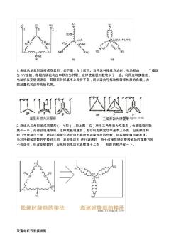
1.绕组从单星形改接成双星形,如下图(左)所示。当用这种接线方式时,电动机由 Y接改 为 YY连接,每相的绕组均由串联改为并联,这样使磁极对数较少了一般。利用这种换接法, 电动机在变极调速后,其额定转矩基本上保持不变,所以适合与拖动恒转矩性质的负载,力 图起重机和皮带传输机等。 2.绕组从三角形改成双星形( Y形),如上图(右)所示三角形改为双星形,也使磁极对数 减小一半,而得到调速效果。这种变极调速后,电动机的额定功率基本上不变,但是额定转 矩几乎要减小一半,所以这种接法适合用于拖动恒功率性质的负载,如各种金属切削机床。 当利用磁极对数的变换对三相 异步电动机 进行调速时,由于改接后绕组旋转磁场的旋转方向 不会改变,在改变极数时,应把接到电动机进线端子上的 电源的相序变一下。 双速电机双星接线图 你数每极每相有多少个槽就可以了, 再用总槽数除以相数, 再除以刚才数的每极每相的槽数, 就是

 电机学答案
电机学答案
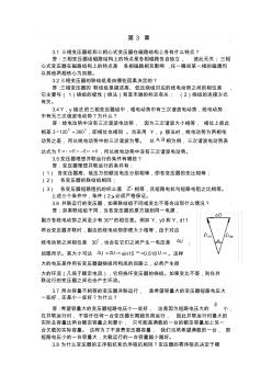
第 3 章 3.1 三相变压器组和三相心式变压器在磁路结构上各有什么特点? 答:三相变压器组磁路结构上的特点是各相磁路各自独立, 彼此无关;三相 心式变压器在磁路结构上的特点是 各相磁路相互影响 ,任一瞬间某一相的磁通均 以其他两相铁心为回路。 3.2三相变压器的联结组是由哪些因素决定的? 答:三相变压器的 联结组是描述高、低压绕组对应的线电动势之间的相位差 , 它主要与( 1)绕组的极性(绕法)和首末端的标志有关; (2)绕组的连接方式 有关。 3.4 Y,y接法的三相变压器组中,相电动势中有三次谐波电动势,线电动势 中有无三次谐波电动势?为什么? 答:线电动势中没有三次谐波电动势, 因为三次谐波大小相等, 相位上彼此 相差 00 3601203 ,即相位也相同 。当采用 Y,y 接法时,线电动势为两相电 动势之差,所以线电动势中的三次谐波为零。 以 BA, 相为例,三次谐波电动势表
《自动化专业系列教材:电机学与拖动基础(第2版)》取材丰富、结构严谨、重点突出、系统性强;各章相对独立,便于读者取舍。每章配有例题,附有足够数量的思考题与习题。
《自动化专业系列教材:电机学与拖动基础(第2版)》第一版是自控、船电类专业本科《电机学与拖动基础》课程用的“九五”规划部委级重点教材。《自动化专业系列教材:电机学与拖动基础(第2版)》为第二版,内容有增删,部分内容的安排作了调整,可供新专业目录的高等学校本科自动化专业、电气工程及其自动化专业、机械电子工程专业和其他相关专业使用,亦可作职业技术学院、专科、成人高等教育同类专业的教材,还可供有关工程技术人员参考。
电工与电机学基础定 价:¥32.00
作 者:林文孚 主编
出 版 社:水利水电出版社
出版时间:2011-8-1
开 本:16开
I S B N:9787508489674
全书共分五章,即直流电机(含直流电动机的拖动) 、变压器、交流旋转电机的共同问题、异步电机(含异步电动机的拖动)和同步电机。每一章分若干节,内容主要是各种电机的原理、结构、特性和应用以及拖动基础,每章分基本知 识点、重点与难点、典型题解析和自我检测题四部分。附录中收录了西安交通大学近年来本科生的电机学期末考试题、硕士研究生入学考试题以及练习题的答案(部分习题有解题过程 )。《电机学(含拖动基础)学习指导典型题解》可作为大学本科生、专科生学习电机学(含拖动)课程的辅导教材;其基本内容作为 高等教育自学考试以及成人高等教育的该课程的自学指导书也很适合;也可作为有关硕士研 究生报考相关专业的复习参考书。
- 相关百科
- 相关知识
- 相关专栏
- 电机及其传动系统——原理、控制、建模和仿真
- 电机及其拖动
- 电机及应用(第2版)
- 电机及拖动基础上册
- 电机及拖动基础学习指导
- 电机及拖动基础实验/实训指导书
- 电机及拖动应用技术
- 电机及拖动技术
- 电机及拖动(第2版)
- 电机及拖动(第3版)
- 电机及控制技术(第2版)
- 电机及控制技术
- 电机及电力拖动基础
- 电机及电气控制实践
- 电机变压器安装与检修
- 电机变压器设备安装与维护(教师用书)
- 云南省基础设施项目投资建设-回购(BT)合同范本
- 以BIM为基础的装配式建筑全生命周期管理问题
- 基于闭环反馈优化的IDC基础设施造价评估模型
- 有软弱下卧层时确定天然地基上基础底面积的简便方法
- 中国电机工程学会高压专业委员会
- 张力式电子围栏周界防范报警系统设计原理及应用现状
- 可关断晶闸管(GTO)直接门极驱动电路
- 在数控机床上通过监视主轴电机负荷实时监控刀具寿命
- 永城火电厂300MW机组给水泵驱动方式的优化选择
- 易地扶贫搬迁安置点公共基础设施施工组织方案与对策
- 以位移为基础的钢筋混凝土桥梁墩柱抗震设计方法
- 云南省基础设施项目投资建设-回购(BT)合同范本
- 以工程和创新能力培养为导向的化工专业基础课程建设
- 厂房设备基础分部分项工程量清单与计价表
- 在役桥梁桩基础受冲刷作用影响的安全评价与分析
- 在浅覆盖土层上的深水基础导管架工作平台设计与施工